TL;DR: Always take into account the ground bounce.
Introduction
I’m developing a software controlled Switched Mode Power Supply (SMPS). For this I need to measure current at ~250kHz. This is a recollection of the false assumptions and mistakes I made.
The circuit
I’ve decided to measure the current lowside as it seemed easier when I stared. And lucky me, this problem has been solved countless times before and the ideas collected in the application note AN105 by LT.
My circuit is basically this:

Figure 26: “Classic” Precision Low Side Current Sense. Source: AN105 by LT
I’ve built it twice: One for forward current, one for backward current. The lowpass capacitor in the feedback path was omitted as my GBP is 4MHz and I’ve got enough parasitics.
Resistors are 1kΩ and 7.5kΩ which results in a gain of
G = 1 + R2 / R1 = 1 + 7500Ω / 1000Ω = 8.5
New best opamp ever
The LM7301 was chosen as operation amplifier. It’s still in the bargain bin but not technologically outdated as the LM358. It has the following specs:
- Wide Supply Range: 1.8 V to 32 V
- Input Common Mode Voltage Range Extends Beyond Rails:
VEE − 0.1 V to VCC + 0.1 V - Rail−to−Rail Output Swing: 0.07 V to 4.93 V at VS = 5 V
- Wide Gain−Bandwidth: 4 MHz
- Low Supply Current: 0.60 mA at VS = 5 V
- High PSRR: 104 dB at VS = 5 V
- High CMRR: 93 dB at VS = 5 V
- Excellent Gain: 97 dB at VS = 5 V
- Capable of Driving a 1 nF Capacitive Load

LM7301 Pinout Source: ON Semiconductor datasheet
I especially like the high speed and that I get down to the bottom rail.
The PCB
This is easy. I quickly built a breadboard circuit for the power and signal. The CPU is on a separate development board. You can see the pinheader connections on the left.

the breadboard
Okay, it looks bad. The signal layer is almost invisible as I used 0.1mm enamel wire. Here is the same picture with some overlay

the breadboard with overlays
I’ve maintained a star connection for power supply everywhere. Except for the opamps as their current and dynamic consumption is negligible (or so I thought).
All modules have their own ceramic bypass capacitors. I minimized current and voltage loops and over sized the inductor, so EMI shouldn’t be a problem. The IR2110 mosfet driver shuts down on undervoltage which means my mosfets won’t release their magic smoke when I do a programming error.
Measurements
I supplied the circuit with 12V and let it run as a buck converter with a 50% duty cycle @250kHz set in my microcontroller. I used a 12V light bulb as load.
But the opamp signals are all wrong! This is the voltage drop over the shunt measured differentially:

Diff signal over shunt. 50mV/div
I just want this signal amplified. And this is the amplified output signal of my forward current opamp:
forward current opamp out 50mV/div
This is much worse than the original signal. A PID controller won’t stand a chance with this, even if I filter the signal.
Even worse is the backward current signal:

backward current opamp out 50mV/div
Which means that even though I have current flowing forward, my backward signal is higher than my forward signal. And heavily distorted.
Failing
I’ve failed somewhere, but I have no idea where. Maybe I’m measuring wrong? It’s still 250kHz at roughly 2.5A and 12V. Should I use a ground spring on my osciloscope probe? Maybe this is all EMI?
Fast forward a few hours of procrastination and countless coffees later:

forward current opamp ground pin 50mV/div
This is the ground pin of the forward current opamp! It’s just the same as it’s signal out! So I’m not measuring a signal, only the ground bounce.
Unfortunately, the backward current opamp’s ground pin is even worse. Which led me to the wrong conclusion that it’s all EMI or my oscilloscope’s probe. After resoldering the opamps with separate supply connections, the backward current opamp’s ground was all fine. So the error has to be with only the forward current opamp.
Solution
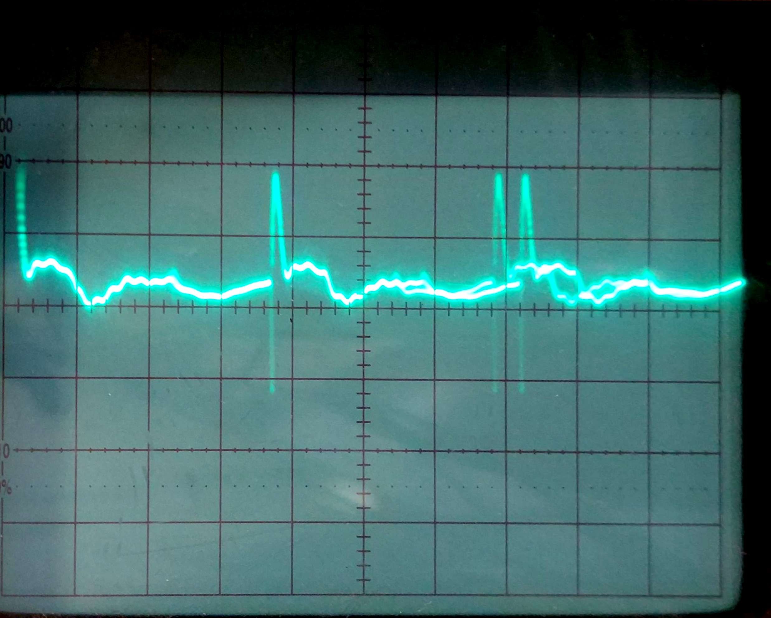
The solution is applying 1V 10A between ground and signal out of the forward current opamp. The tiny invisible copper piece lodged under the case quickly dissolved into smoke. Afterwards, I got this signal:

forward current opamp out 50mV/div
Just what I wanted! I can digitize and filter this signal a bit. Then I can throw the one-size-fits-all PID controller on it and I’m all fine. Back to coding!
The nodes in this picture are probably from the freewheeling diode in the lower mosfet. I didn’t enable synchronous rectification yet. Which means that, if the buck converter is in continuous mode, the diode will bear forward current when the upper mosfet is turned on. These diodes are not as fast as Schottky diodes. The reverse recovery time leads to a near short circuit. Luckily we have all those parasitic inductance built-in which leads to just a bit of ringing instead of magic smoke leaving the parts.
Conclusion
- always maintain a star connection. It’s also important for debugging
- always means always and not if you see a reason for it in this specific case
- my oscilloscope wants a differential probe
- current measurement in the ground line is no good because you throw together the signal and the power. Next time, I’ll just measure high side because then I have to treat it as an varying potential – which ground is in practice