TL;DR: A tiny code sample which shows how to measure capacity with one port pin
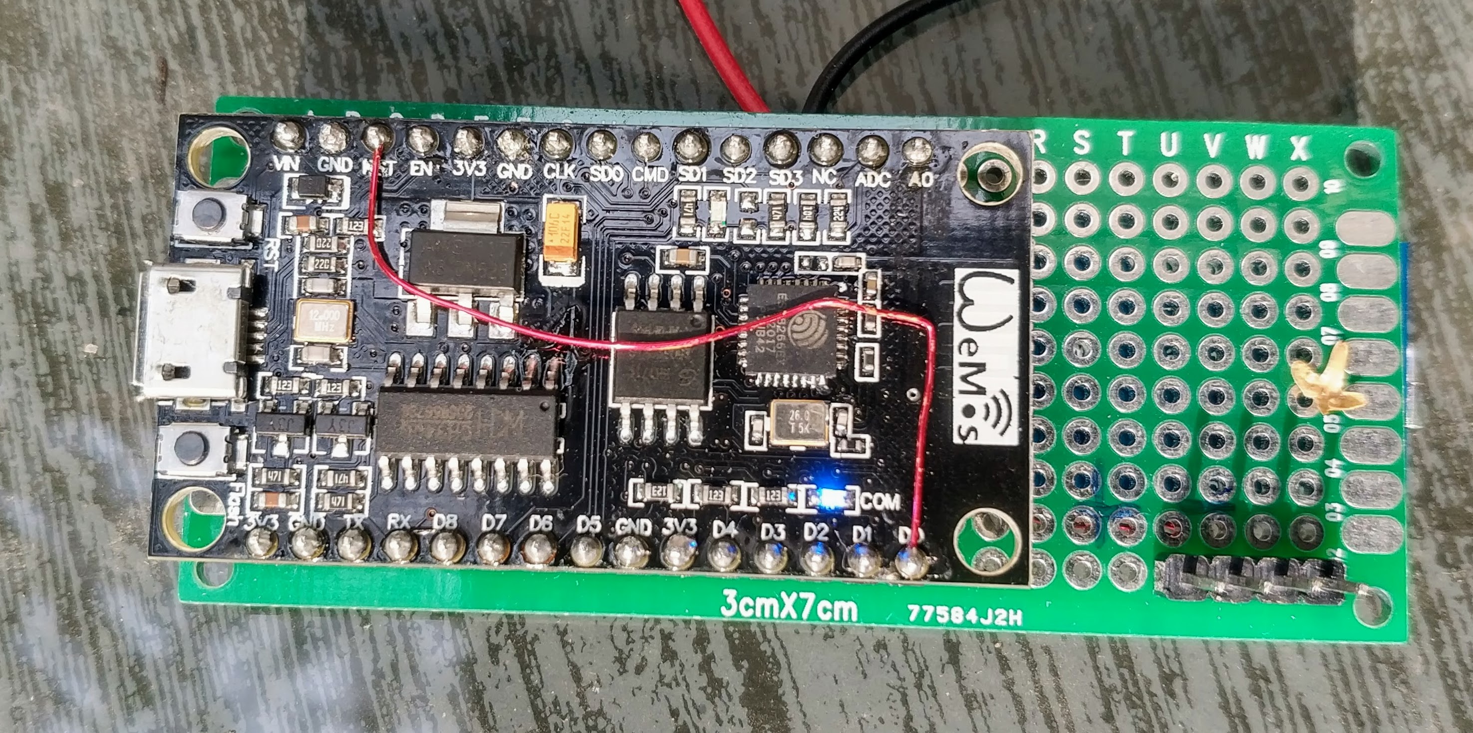
The ESP8266 module is now everywhere. With platformio you also have a simple setup and environment.
But I had some problems measuring the capacity with this device. We are talking here about pF – nF, because I am interested in capacitive touch and the measurement of the capacitance of some cables.
S&H ADC
With the Arduino you can abuse the sample & hold capacitor of the internal ADC. This allows you to transfer the charge from the test capacitor to the S&H capacitor and, after conversion, obtain a voltage value representing the capacitance. The concept is explained here by microchip.
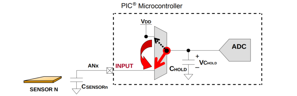
Charge Transfer with the Sample & Hold capacitor of an ADC. Source: Figure 2 of AN1298 by Microchip
With the ESP8266 this is not possible. The ADC pin is not a GPIO.
QTouch
What you can do is to add a tank capacitor between two pins and charge this capacitor until the ESP module detects a high value. It’s like carrying water into a known large tank with a small, unknown bucket. The number of small bucket fills is reciprocal to the volume of the smaller bucket (capacity). Atmel calls this QTouch, but the concept has been around for a long time.
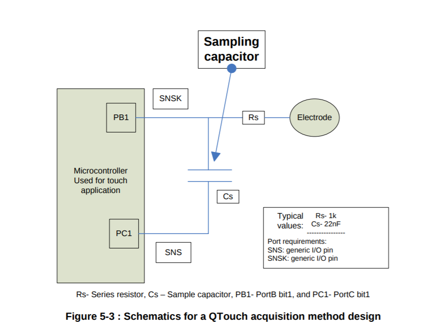
Rough schematic. You can see the Cs capacitor which will be filled by the electrode capacitor.
Source: Figure 5-3 of the Atmel QTouch Library User Guide http://dl.btc.pl/kamami_wa/atavrqtouchx_qtouch_library_user_guide.pdf
I no longer use the QTouch method, but I still have some code left around where I tried to explain the concept to myself. I’m not sure if this still works and it is untested. I include it as a starting point for you.
/*
 * qtouch implementation using two port pins. Source for idea with pictures:
 * https://www.mikrocontroller.net/topic/156809#1485377
 *
 "The QTouch™ acquisition method charges an electrode of unknown
 capacitance to a known potential. The resulting charge is transferred
 into a measurement capacitor (Cs). The cycle is repeated until the
 voltage across Cs reaches a voltage. The signal level is the number of
 charge transfer cycles it took to reach the voltage. Placing a finger on
 the touch surface introduces external capacitance that increases the
 amount of charge transferred each cycle, reducing the total number of
 cycles required for Cs to reach the voltage. When the signal level
 (number of cycles) goes below the present threshold, then the sensor is
 reported as in detect." source: Atmel Qtouch Documentation
 *
 * The following steps have to be executed for each measurement:
 * 1. set the sensor plate and the comparative pin to 0
 * 2. set all pins to open to avoid cross conduction
 * 3. charge the sensor plate to 1
 * 4. set all pins to open to avoid cross conduction
 * 5. set the sensor pin to 0
 * 6. do this while the capacitive plate pin is 0
 */
uint32_t getCapacitiveSense() {
	const auto sensorPin = 5;
	const auto tankCapacitorPin = 4;
	const uint32_t chargeCyclesMax = 65535;

	// step 1: set all pins to output and low
	pinMode(sensorPin, OUTPUT);
	digitalWrite(sensorPin, LOW);

	pinMode(tankCapacitorPin, OUTPUT);
	digitalWrite(tankCapacitorPin, LOW);

	const uint32_t maxCycles = 65535;
	uint32_t retValue = maxCycles;// this will be returned if nothing is detected
	for (uint32_t i = maxCycles; i > 0; i--) {
		// step 2: set all pins to float
		pinMode(sensorPin, INPUT);
		pinMode(tankCapacitorPin, INPUT);

		// step 3: charge the sampling capacitor  to 1
		digitalWrite(tankCapacitorPin, HIGH);
		pinMode(tankCapacitorPin, OUTPUT);

		// step 4: set all pins to open to avoid cross conduction
		pinMode(sensorPin, INPUT);
		pinMode(tankCapacitorPin, INPUT);

		// step 5: set the capacitive plate to 0
		pinMode(sensorPin, OUTPUT);
		digitalWrite(sensorPin, LOW);

		// stop the loop if the capacitor is charged
		if (digitalRead(tankCapacitorPin)) {
			retValue = maxCycles - i;
			break;
		}
	}

	// clean up and discharge everything
	pinMode(tankCapacitorPin, OUTPUT);
	digitalWrite(tankCapacitorPin, LOW);
	pinMode(sensorPin, OUTPUT);
	digitalWrite(sensorPin, LOW);

	return retValue;
}
Measure RC-constant tau directly
But there is another way! You can simply charge the capacitor and measure the time! Unfortunately, this is really short. So I tested a little function that measures time pretty accurately. Here it is:
// magic keywords which make this function a bit faster
static int ICACHE_RAM_ATTR __attribute__((optimize("Ofast"))) capSense() {
	auto pin1 = 4;
	digitalWrite(pin1, LOW);
	pinMode(pin1, OUTPUT);
	yield();		// let the wifi do it's stuff one last time before disabling interrupts
	system_update_cpu_freq(160);	// overclock to get more resolution

	noInterrupts();
	auto start = ESP.getCycleCount();

	GPIO_DIS_OUTPUT(pin1); // use native esp-sdk functions here for performance
	PIN_PULLUP_EN(PERIPHS_IO_MUX_GPIO4_U);	// enable the pullup and charge the external capacitor with it

	while (!(GPIO_REG_READ(GPIO_IN_ADDRESS) & (1 << pin1))) {
		;	// wait until the pin has reached a high level at ~0.8 * VCC
	}
	auto end = ESP.getCycleCount();
	system_update_cpu_freq(80); // go back to normal
	interrupts();	// pray that no wifi packet arrived in the meantime
	return end - start;
}
The auto keyword is c++11, if you want to use outdated software, you can simply replace it with int or similar.
Hardware measurements
So this gives me a value of 188 with just the PCB and some wire wrap. But what does this look like in the real world? What’s happening?
Here are some oscilloscope shots which hopefully explain this more.
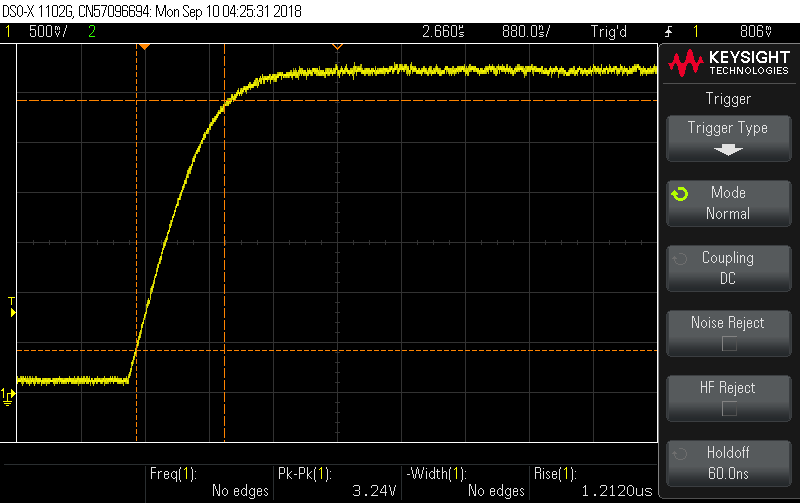
1.2µs rise time = 254 clock cycles
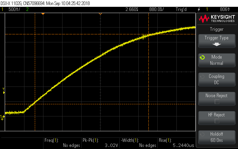
5.2µs rise time = 548 clock cycles
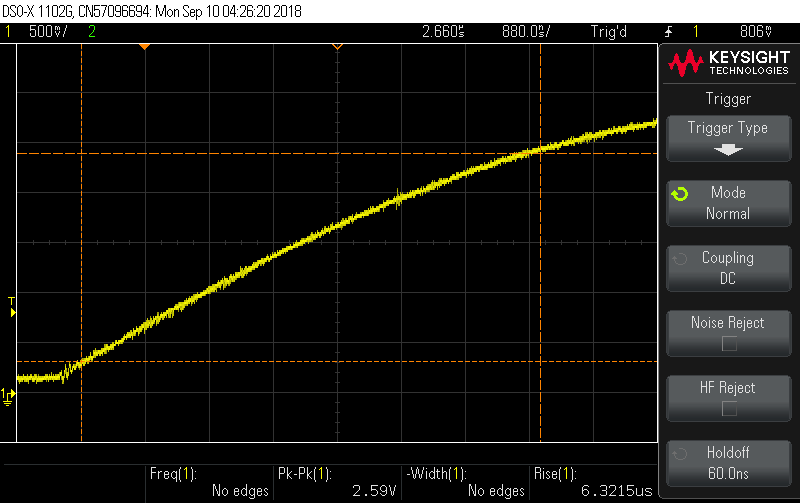
6.3µs rise time = 804
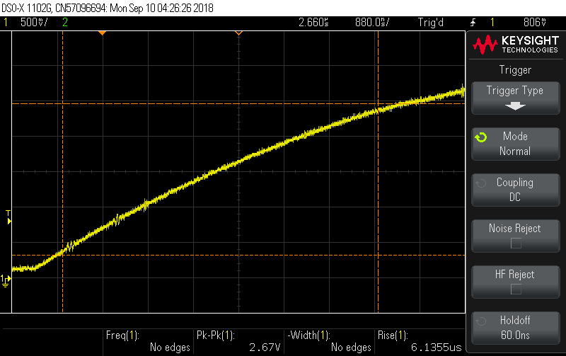
6.1µs rise time = 804 clock cycles
(I just picked 804 out of a huge line of values. 804 is somewhere in the middle)